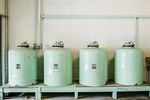
Separator Vessels in Oil & Gas: Guide to Design, Operation, and Practical Insights
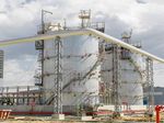
Separator Vessels in Oil & Gas are process vessels used to separate mixtures of hydrocarbons, water, and gas into different phases. They are widely used in upstream production facilities, gas processing plants, refineries, offshore platforms, and other petroleum-processing environments.
When fluids come from an oil or gas well, they can contain several materials together. A production stream may contain crude oil, natural gas, produced water, sand, and other substances. A separator creates controlled conditions that allow these components to separate based on differences in density and physical behavior.
The separated phases can then move to different parts of the processing system. Gas may continue toward compression or gas treatment, liquid hydrocarbons may move toward stabilization or further processing, and produced water may enter an appropriate treatment system.
How Separation Takes Place
The basic separation process relies on reducing the velocity of the incoming fluid and providing enough space for different phases to move apart.
Gas is generally lighter than liquid, so it rises toward the upper section of a vessel. Heavier liquid phases settle toward the bottom. When oil and water are both present, their density difference can allow them to form separate liquid layers.
Inside a separator, several physical effects may occur:
Inlet momentum reduction: The incoming stream is slowed and redirected.
Gravity separation: Different phases move according to their densities.
Droplet settling: Larger liquid droplets fall out of the gas stream.
Gas disengagement: Gas separates from the liquid phase.
Liquid retention: The vessel provides sufficient residence time for liquid phases to separate.
Mist removal: Internal devices capture small liquid droplets carried with gas.
The exact arrangement depends on the composition, pressure, temperature, flow rate, and required separation performance.
Main Types of Separator Vessels
Two-phase separators separate gas from liquid. They are commonly used when the incoming stream mainly contains a gas phase and a combined liquid phase.
Three-phase separators separate gas, oil, and water. Internal design allows the two liquid phases to form separate layers.
Horizontal separators provide a relatively long liquid-gas interface and can be useful where liquid separation and retention are important.
Vertical separators use a vertical arrangement in which gas moves upward while liquid accumulates in the lower section. They can be useful where floor space is limited or where the incoming stream contains substantial gas.
Spherical separators use a compact vessel geometry. They have been used in selected applications but are less common for many modern processing arrangements.
API Recommended Practice 12J specifically addresses the process design of oil and gas separators and scrubbers, providing an important industry reference for separator design.
Importance
Supporting Oil and Gas Processing
Separator Vessels in Oil & Gas are important because downstream equipment generally requires a controlled feed. Gas compressors, pumps, heat exchangers, dehydration equipment, stabilizers, and other process units can be affected by unwanted liquid or gas entering the wrong process stream.
A separator therefore acts as an important transition point between well fluids and subsequent processing stages.
Protecting Downstream Equipment
Liquid droplets carried into a gas compressor can create operational problems, while excessive gas entering equipment intended primarily for liquid handling can also cause difficulties.
Gas-liquid separation can reduce the amount of unwanted material entering downstream equipment when the vessel and its internal components are appropriately designed.
Managing Production Fluids
Oil and gas production streams can change over time. Water production may increase, gas-liquid ratios can vary, and flow conditions can change with reservoir and operating conditions.
Separator design therefore needs to account for expected operating ranges rather than only one fixed production condition.
Supporting Measurement
Separating different phases can also help downstream measurement and process control. Once gas, oil, and water are directed into appropriate streams, flow rates and operating conditions can be monitored more effectively.
Main Design Parameters
| Parameter | Why It Matters | Typical Design Consideration |
|---|---|---|
| Pressure | Determines operating conditions | Operating and design pressure |
| Temperature | Influences fluid behavior | Normal and design temperature |
| Flow rate | Determines vessel capacity | Minimum, normal, and maximum flow |
| Fluid density | Influences separation | Gas, oil, and water densities |
| Droplet size | Affects separation performance | Expected droplet distribution |
| Residence time | Allows phase separation | Liquid retention requirements |
| Vessel geometry | Influences flow behavior | Horizontal or vertical arrangement |
| Material selection | Supports mechanical integrity | Fluid chemistry and temperature |
Recent Updates
Updated Separator Design Guidance
The oil and gas industry continues to maintain and revise technical standards covering separation equipment. API's current standards plan lists API RP 12J, Process Design of Oil and Gas Separators and Scrubbers, 9th edition, with publication activity recorded in 2024. This shows continued attention to process design requirements for separator and scrubber equipment.
The guidance is relevant to engineers evaluating vessel dimensions, separation principles, operating conditions, and related process considerations.
Greater Attention to Pressure Integrity
Separator vessels operate under pressure, making mechanical integrity a central design consideration. Pressure-vessel engineering commonly addresses wall thickness, materials, welds, pressure testing, inspection, corrosion, and pressure-relief arrangements.
ASME BPVC Section VIII provides requirements for pressure-vessel design, fabrication, examination, inspection, and testing. ASME identifies Section VIII as a major code framework for pressure vessels used in demanding process environments.
Digital Process Monitoring
Modern oil and gas facilities increasingly use digital instrumentation to monitor separator pressure, temperature, liquid level, flow, and other process conditions.
Control systems can collect information from transmitters and other instruments and display operating conditions to plant personnel. Historical data can also help engineers examine process behavior and identify unusual operating patterns.
Improved Instrumentation
Level measurement is particularly important in separators because incorrect liquid levels can affect phase separation and downstream equipment.
Modern installations may use different measurement technologies depending on the fluid properties and operating conditions. Redundant instruments may also be used where process safety requirements justify them.
Pressure Relief and Depressurization
Pressure relief remains an important part of process-vessel design. API Standard 521 provides guidance for pressure-relieving and vapor-depressuring systems used in petroleum production facilities, gas plants, petrochemical facilities, and related installations.
Relief systems are designed according to the applicable process hazards, vessel conditions, credible overpressure scenarios, and governing engineering requirements.
More Detailed Inspection Practices
Inspection remains an important part of the separator lifecycle. API Recommended Practice 572 addresses inspection practices for pressure vessels and provides guidance relevant to inspection planning and evaluation.
Inspection programs may consider corrosion, erosion, cracking, weld condition, thickness measurements, pressure boundaries, internal components, and other degradation mechanisms.
Laws or Policies
International Standards Framework
There is no single worldwide law governing every separator vessel. Requirements depend on the country, facility type, operating environment, and applicable regulatory authority.
However, international oil and gas facilities commonly use recognized engineering standards such as API publications, ASME Boiler and Pressure Vessel Code, ISO standards, and national regulations.
API states that its standards are used internationally and that its standards and recommended practices address safety, environmental protection, and technical requirements across the natural gas and oil industry.
Pressure Vessel Requirements
Pressure-vessel regulations generally address design, fabrication, inspection, testing, certification, operation, and periodic examination.
For example, India's PESO framework for applicable static and mobile pressure vessels recognizes design codes including BIS 2825, ASME Section VIII, and PD 5500 under specified regulatory conditions.
Other countries may use their own pressure-equipment legislation while referencing international standards.
Process Safety
Oil and gas facilities also need to address hazards associated with flammable hydrocarbons, high pressure, high temperature, toxic gases, corrosion, and uncontrolled releases.
Process safety frameworks can include hazard identification, operating procedures, emergency shutdown systems, pressure relief, gas detection, fire protection, inspection programs, and management of changes.
Offshore Installations
Offshore separator vessels may face additional requirements because of restricted space, marine conditions, platform movement, evacuation limitations, and environmental exposure.
National offshore regulators, classification organizations, and international standards may all contribute to the applicable design framework.
Inspection and Integrity Management
Pressure vessels require continued attention after installation. Inspection intervals and methods depend on applicable regulations, vessel condition, materials, operating environment, and facility procedures.
Integrity-management programs can combine inspection records, thickness measurements, corrosion monitoring, process data, and engineering assessments.
Tools and Resources
Process Simulation Software
Process simulation programs can model pressure, temperature, flow rates, phase behavior, and other operating conditions.
Engineers can use these models during process design to understand how changes in feed composition or operating conditions may influence separation.
Separator Sizing Calculations
Engineering calculations can evaluate vessel diameter, length, liquid retention, gas velocity, droplet settling, and other parameters.
Actual sizing should be performed using appropriate engineering methods and project-specific data rather than a single general formula.
Process Flow Diagrams
A Process Flow Diagram, or PFD, shows major equipment and process streams. It helps engineers understand where the separator sits within the overall production or processing system.
Piping and Instrumentation Diagrams
A Piping and Instrumentation Diagram, commonly called a P&ID, provides more detailed information about piping, valves, instruments, control loops, and safety equipment around the vessel.
Pressure and Level Instruments
Typical separator instrumentation can include:
Pressure transmitters: Monitor vessel pressure.
Temperature transmitters: Monitor process temperature.
Level transmitters: Monitor liquid accumulation.
Flow meters: Measure gas or liquid movement.
Pressure relief devices: Provide protection against specified overpressure conditions.
Control valves: Regulate selected process streams.
Industry Standards and Regulatory Resources
Engineers can consult API standards, ASME codes, ISO publications, national pressure-equipment regulations, offshore rules, and regulator guidance.
API provides an online reading room containing selected standards incorporated by reference into regulations, while ASME provides information about its pressure-vessel code framework.
FAQs
What are Separator Vessels in Oil & Gas?
Separator Vessels in Oil & Gas are pressure vessels used to separate gas, oil, water, and other phases from production or process streams.
How do Separator Vessels in Oil & Gas work?
Separator Vessels in Oil & Gas slow and redirect incoming fluid so that gas and liquid phases can separate. Gravity, residence time, vessel geometry, and internal components contribute to the separation process.
What is the difference between a two-phase and three-phase separator?
A two-phase separator generally separates gas from liquid, while a three-phase separator is designed to separate gas, oil, and water into distinct streams.
What factors affect separator vessel design?
Important factors include pressure, temperature, flow rate, fluid composition, density, viscosity, expected droplet size, residence time, corrosion conditions, vessel orientation, and required separation performance.
Which standards are used for separator vessels?
Common international references include API RP 12J for separator and scrubber process design, ASME BPVC Section VIII for pressure-vessel engineering, and API guidance for pressure relief and inspection. Applicable national regulations must also be considered.
Conclusion
Separator Vessels in Oil & Gas provide an important separation stage between production fluids and downstream processing equipment. Their design involves fluid behavior, vessel geometry, pressure integrity, instrumentation, internal components, and process safety. Recent developments include updated industry guidance, improved instrumentation, digital monitoring, and greater attention to inspection and pressure integrity. Because requirements differ across countries and facilities, separator projects need to follow the applicable engineering standards, regulatory requirements, and site-specific process conditions.