Coordinate Measuring Machines: Guide to Precision Measurement and Inspection
Coordinate Measuring Machines, commonly called CMMs, are precision measurement systems used to determine the size, shape, position, and geometric characteristics of physical objects. They are widely used in manufacturing, engineering, aerospace, automotive, medical-device production, electronics, and other industries where dimensional accuracy is important.
A CMM measures points on an object's surface within a three-dimensional coordinate system. The machine records the position of each measured point along three axes, commonly identified as X, Y, and Z. Specialized software then uses these points to calculate dimensions, angles, distances, geometric relationships, and other characteristics.
For example, a manufacturer producing a metal component may need to confirm that a hole is located at the correct position, that two surfaces are properly aligned, or that the overall dimensions match a digital design. A CMM can collect measurement data and compare it with specified dimensions or a computer-aided design model.
How Coordinate Measuring Machines Work
A typical CMM includes several major components:
Machine structure: Provides a stable framework for movement.
Coordinate axes: Allow the measurement system to move along different directions.
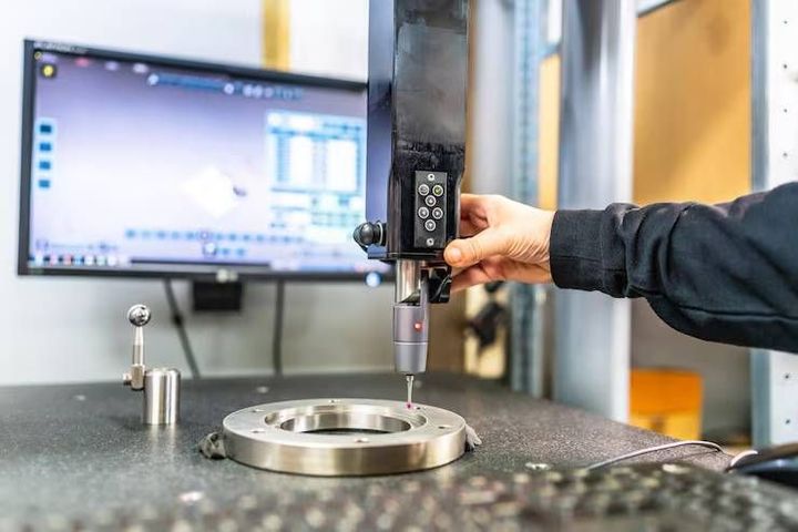
Probe: Detects or scans the surface being measured.
Controller: Coordinates machine movement and measurement signals.
Software: Converts collected points into dimensional and geometric results.
Measurement table: Supports the component during inspection.
During a measurement process, the component is positioned on the machine table. The probe then moves to selected locations and collects coordinate information.
Depending on the system, the probe may physically touch the surface or use optical, laser, or other non-contact techniques. The resulting point cloud or measurement data can then be analyzed using inspection software.
Main Types of CMMs
Bridge CMMs use a bridge structure that moves across a measurement table. They are widely associated with high-precision dimensional inspection.
Gantry CMMs use a larger structure that can accommodate very large components. They can be used for applications involving large automotive, aerospace, industrial, or structural parts.
Horizontal-arm CMMs position the measurement arm horizontally and can be useful for larger components and body structures.
Portable CMMs are designed to be moved around a facility or taken closer to the component. Portable coordinate-measurement technologies include articulated arms and optical systems.
Optical CMMs use cameras, optical sensors, lasers, or other non-contact measurement methods. These systems can be useful for small, delicate, or complex components where physical contact is undesirable.
Importance
Supporting Dimensional Inspection
Manufactured components often need to remain within specified dimensional limits. A CMM can measure features such as length, diameter, height, hole location, surface position, and other geometric characteristics.
This information can be compared with engineering drawings, CAD models, or specified tolerances.
Measuring Complex Geometries
Some components contain curved surfaces, multiple holes, angled features, or complicated three-dimensional shapes. Conventional measuring tools may not capture every characteristic efficiently.
Coordinate Measuring Machines can collect numerous points across complex surfaces and use software to analyze their geometric relationships.
Supporting Manufacturing Quality
Measurement data can help manufacturers determine whether components conform to defined specifications. CMM inspection may be performed during production, after machining, during final inspection, or during investigation of dimensional variation.
The resulting data can also provide information for manufacturing-process analysis.
Supporting Reverse Engineering
A CMM can collect dimensional information from an existing physical component. When combined with appropriate software, these measurements can contribute to the creation or verification of a digital representation.
This can be useful when analyzing legacy components, checking existing parts, or documenting physical geometry.
Common Measurement Characteristics
| Measurement | What It Examines | Example |
|---|---|---|
| Linear dimension | Distance between features | Part length |
| Diameter | Circular feature size | Hole diameter |
| Position | Feature location | Hole center |
| Flatness | Surface variation | Flat mounting surface |
| Roundness | Circular form | Shaft section |
| Perpendicularity | Relationship between features | Vertical face |
| Parallelism | Alignment between surfaces | Two parallel faces |
| Profile | Shape of a surface | Curved component |
Recent Updates
Integration With Digital Manufacturing
Coordinate Measuring Machines are increasingly connected with digital manufacturing environments. Measurement results can move from inspection software into broader quality and production systems.
This can create a more connected flow between CAD models, manufacturing processes, inspection activities, and quality records.
Automated Measurement
Automated CMM programs can repeat defined measurement routines across batches of components. Once an appropriate inspection program has been created and validated, the machine can follow programmed measurement paths with limited manual intervention.
Automation can be particularly useful when many similar components require repeated inspection.
Optical and Non-Contact Measurement
Optical measurement technologies continue to expand the capabilities of dimensional inspection. Cameras, structured light, laser scanners, and other sensors can capture large numbers of points without requiring physical contact with every surface.
Non-contact measurement can be useful for delicate components, soft materials, complex surfaces, or applications where rapid surface data collection is important.
Portable Measurement Technologies
Portable coordinate measurement systems provide greater flexibility than fixed laboratory-style machines. Articulated arms, portable scanners, laser trackers, and other systems can be positioned close to large or difficult-to-move components.
This is particularly relevant to aerospace, automotive, shipbuilding, heavy equipment, and large-scale industrial manufacturing.
Artificial Intelligence and Automated Analysis
Artificial intelligence and advanced software techniques are being explored for inspection planning, image processing, pattern recognition, anomaly detection, and measurement-data analysis.
AI does not replace the fundamental need for traceable measurement methods. Measurement uncertainty, calibration, environmental conditions, reference standards, and appropriate inspection procedures remain important.
Model-Based Inspection
Manufacturers increasingly use three-dimensional CAD models as references for inspection planning. Instead of relying only on separate two-dimensional drawings, measurement software can associate inspection characteristics with features represented in a digital model.
This approach can help connect product design, manufacturing, and inspection information.
Standards and Measurement Traceability
International measurement practices continue to emphasize calibration, traceability, uncertainty evaluation, and standardized methods.
The ISO 10360 series remains an important family of standards for acceptance and periodic reverification tests of coordinate-measuring systems. Different parts address different CMM configurations and measurement capabilities.
The growing use of automated and optical systems also increases the importance of selecting appropriate verification procedures for the specific measurement technology.
Laws or Policies
International Measurement Standards
CMM operation is influenced primarily by technical standards, quality requirements, customer specifications, and industry-specific rules rather than one universal law governing every machine.
The ISO 10360 series provides internationally recognized requirements and testing methods for evaluating the performance of coordinate-measuring systems.
Organizations may also use standards such as ISO 9001 for quality-management systems and other sector-specific frameworks depending on their activities.
Calibration and Traceability
Reliable dimensional measurement depends on traceability to recognized measurement references. Calibration establishes the relationship between measurement equipment and reference standards under defined conditions.
The International Laboratory Accreditation Cooperation (ILAC) provides information concerning laboratory accreditation and measurement traceability, while national metrology organizations maintain measurement standards within individual countries.
Aerospace and Automotive Requirements
Highly regulated sectors can have additional measurement and quality requirements. Aerospace manufacturers, automotive manufacturers, medical-device producers, and other industries may specify particular inspection methods, documentation, calibration intervals, or measurement capabilities.
Organizations must therefore consider both general measurement standards and requirements applicable to their specific industry and customer relationships.
Environmental Conditions
Temperature can influence dimensional measurement because materials expand and contract with changes in temperature. Vibration, humidity, dust, machine stability, and component temperature can also influence measurement conditions.
CMM laboratories therefore commonly control environmental conditions according to the machine's specifications and applicable measurement procedures.
Measurement Uncertainty
A measurement result is not simply a number without limitations. Measurement uncertainty represents the range of doubt associated with the measurement process.
Factors can include machine performance, probe characteristics, temperature, calibration standards, operator procedures, workpiece conditions, and data-processing methods.
Understanding uncertainty is particularly important when measured dimensions are close to specified tolerance limits.
Tools and Resources
CMM Inspection Software
CMM software controls measurement routines and analyzes collected coordinate data. It can calculate dimensions, geometric characteristics, surface profiles, and relationships between features.
Some platforms can also compare measured components against CAD models.
CAD Models
Computer-aided design models provide digital descriptions of component geometry. CMM software can use CAD information to help create inspection routines and compare measured geometry against design requirements.
Touch-Trigger Probes
Touch-trigger probes collect measurements when the probe contacts a selected surface. They are commonly used for discrete point measurements.
Scanning Probes
Scanning probes continuously collect surface information as they move across a component. This can produce more detailed geometric information than individual touch points for suitable applications.
Laser Scanners
Laser-based systems can collect large numbers of surface points rapidly. They are particularly useful for complex shapes, large areas, and applications where non-contact measurement is appropriate.
Optical Systems
Camera-based measurement systems use images and optical information to determine selected dimensions and geometric characteristics.
They can be useful for small components, electronic parts, flat features, and other applications suited to optical inspection.
Calibration Standards
Reference artifacts, calibrated gauges, spheres, step gauges, and other standards can be used during CMM verification and calibration activities.
The appropriate reference depends on the CMM configuration, measurement method, applicable standard, and required accuracy.
FAQs
What are Coordinate Measuring Machines used for?
Coordinate Measuring Machines are used to measure the dimensions, positions, shapes, and geometric relationships of manufactured components. They are widely used for dimensional inspection and quality verification.
How do Coordinate Measuring Machines work?
A CMM determines the coordinates of selected points on a component using a probe or non-contact sensor. Software analyzes those coordinates to calculate dimensions and geometric characteristics.
What are the main types of CMMs?
Common types include bridge, gantry, horizontal-arm, and portable coordinate-measurement systems. Optical and scanning systems provide additional measurement approaches.
Are Coordinate Measuring Machines used in aerospace and automotive manufacturing?
Yes. CMMs are widely used in industries where dimensional accuracy and geometric verification are important, including aerospace, automotive, precision engineering, electronics, and medical-device manufacturing.
What standard is used for CMM performance?
The ISO 10360 series provides internationally recognized acceptance and reverification tests for coordinate-measuring systems. The appropriate part depends on the specific type and measurement technology of the system.
Conclusion
Coordinate Measuring Machines provide a structured way to measure three-dimensional components and evaluate their dimensions and geometric characteristics. Fixed bridge systems, large gantry machines, portable equipment, optical systems, and scanning technologies allow CMM technology to address different inspection requirements. Modern developments include automated inspection, CAD-based measurement, digital manufacturing integration, optical sensing, portable systems, and advanced data analysis. International standards, calibration, environmental control, and measurement traceability remain important for producing reliable dimensional results.