Coaxial Connectors Guide: Types, Applications, and Technical Specifications
A coaxial connector is an electrical component that joins a coaxial cable to another cable, device, or electronic circuit.
Coaxial cables contain a central conductor, an insulating layer, a surrounding metallic shield, and an outer protective jacket. This structure helps carry radio frequency (RF) signals while limiting interference from external electrical sources.
Coaxial connectors are used in telecommunications, broadcasting, laboratory equipment, wireless networks, radar systems, and industrial electronics. Their design allows signals to pass between connected components while maintaining the electrical characteristics required by the application. Coaxial connector manufacturers produce different designs to support variations in frequency, impedance, physical dimensions, and environmental conditions.
The connector selected for a system can affect signal transmission, mechanical stability, and the amount of unwanted reflection at the connection point. RF coaxial connector suppliers therefore work with different connector families and specifications for applications ranging from general electronic equipment to microwave systems.
Common Types of Coaxial Connectors
Several connector types are used across electronic and communication systems. Each has specific mechanical characteristics and electrical operating limits.
SMA connectors: Small threaded connectors frequently used in RF equipment, antennas, test instruments, and microwave circuits.
BNC connectors: Bayonet-style connectors that attach through a short turning motion. They are common in laboratory instruments, video equipment, and some communication systems.
N-type connectors: Threaded connectors used in radio equipment, antennas, and applications requiring robust mechanical connections.
TNC connectors: Threaded versions of a connector family related to BNC, used in selected RF and communication applications.
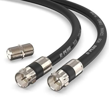
F-type connectors: Commonly used for television signals, cable distribution, and related broadband installations.
SMB connectors: Compact connectors that use a snap-on coupling mechanism and appear in certain communication and electronic assemblies.
Not every connector is compatible with every coaxial cable or device. Physical dimensions, impedance, coupling mechanisms, and operating frequency must be considered together.
Understanding Technical Specifications
Coaxial connectors are commonly described by several technical parameters. These specifications help engineers determine whether a connector suits a particular signal path.
Impedance is one important parameter. Many RF systems use 50-ohm connectors, while television and cable distribution systems commonly use 75-ohm designs. Connecting components with mismatched impedance can cause signal reflections and affect system performance.
Frequency range indicates the range over which a connector is designed to operate under specified conditions. Other relevant parameters include insertion loss, return loss, voltage standing wave ratio (VSWR), power handling, temperature range, and mechanical durability.
Importance
Coaxial connectors matter because electronic systems depend on reliable signal transmission between cables, antennas, instruments, and other devices. A poorly matched or damaged connector can introduce signal reflections, increase transmission loss, or allow unwanted interference into a circuit.
These effects can influence wireless communication, television reception, measurement accuracy, and the operation of industrial monitoring equipment. Selecting a connector with appropriate electrical and mechanical characteristics helps maintain the intended behavior of the complete system.
Applications Across Different Industries
High frequency coaxial connectors are used in systems that transmit signals over relatively broad frequency ranges. Their applications include wireless communication equipment, satellite electronics, antenna assemblies, and radio frequency testing.
Industrial coaxial cable connectors appear in monitoring equipment, communication interfaces, automated test systems, and selected machine-control installations. In these settings, the connector may need to withstand vibration, repeated connection cycles, dust, or temperature changes.
Microwave coaxial connector systems support applications operating at microwave frequencies, including radar equipment, communication links, and laboratory measurement instruments. Their electrical performance can be particularly sensitive to connector geometry, assembly quality, and manufacturing tolerances.
Factors That Influence Connector Selection
Several factors determine whether a connector is appropriate for a specific application.
Frequency range: The connector must support the frequencies used by the system.
Impedance: The connector should match the intended impedance of the cable and connected equipment.
Connection method: Threaded, bayonet, and snap-on designs have different installation and handling characteristics.
Environmental conditions: Moisture, vibration, temperature, and exposure to contaminants can affect connector selection.
Mechanical dimensions: Available space and cable diameter influence the physical design.
Electrical performance: Insertion loss, return loss, shielding, and power ratings may be relevant depending on the application.
These factors are particularly important when designing compact RF equipment or systems that operate at higher frequencies.
Recent Updates
Recent developments in coaxial connector technology reflect the continued expansion of wireless communication, high-speed electronic testing, satellite systems, and compact RF equipment. The general direction is toward smaller components, improved manufacturing consistency, and connector designs that support increasingly demanding signal requirements.
High-Frequency and Precision Designs
High-frequency applications require careful control of connector dimensions and electrical characteristics. Small geometric differences can affect impedance continuity and signal reflections, particularly as operating frequencies increase.
Precision RF connector manufacturers produce components for applications where repeatable measurements and controlled electrical performance are important. Such components may be used in laboratory calibration equipment, microwave testing, communications research, and high-frequency electronic assemblies.
Compact Equipment and Custom Assemblies
Electronic devices increasingly combine multiple functions within limited physical space. This creates demand for compact connectors and cable assemblies that fit particular mechanical layouts without compromising the required electrical specifications.
Custom coaxial connector assemblies may include selected connector types, cable lengths, protective features, and termination methods. Their suitability depends on the application's electrical requirements, mechanical arrangement, and environmental conditions.
Manufacturing and Quality Considerations
Manufacturing processes continue to focus on dimensional accuracy, material consistency, contact quality, and repeatable assembly. Inspection methods may include dimensional measurement, continuity testing, and RF measurements.
SMA coaxial connector suppliers and BNC coaxial connector manufacturers may work with different product configurations, but the same general principle applies: the specified electrical limits must be considered alongside physical compatibility. Product documentation is important because connectors within the same family may have different frequency ratings or environmental characteristics.
| Specification | Meaning | Why It Matters |
|---|---|---|
| Impedance | Electrical resistance to alternating signal flow, expressed in ohms | Helps maintain compatibility across the signal path |
| Frequency range | Supported operating frequencies | Defines the intended application range |
| Insertion loss | Signal power lost through a connection | Helps evaluate transmission efficiency |
| Return loss | Measure of signal reflection at a discontinuity | Indicates impedance matching performance |
| VSWR | Ratio describing standing-wave behavior | Helps assess reflections in an RF system |
| Power rating | Defined power-handling limit under specified conditions | Helps prevent operation beyond stated limits |
| Environmental rating | Specified resistance to environmental conditions | Supports appropriate installation choices |
Tools and Resources
Technical documents and measurement tools help users understand connector compatibility and performance. Manufacturers' datasheets generally provide information about dimensions, materials, frequency limits, impedance, environmental ratings, and recommended assembly procedures.
Connector Selection and Measurement Tools
Several resources are useful when evaluating coaxial connector systems:
Manufacturer datasheets: Provide connector dimensions, electrical ratings, and installation requirements.
Connector compatibility charts: Help identify matching connector interfaces, impedance types, and cable configurations.
RF calculators: Support calculations involving wavelength, frequency, impedance, and transmission-line behavior.
Vector network analyzers: Measure parameters such as return loss, insertion loss, and S-parameters.
Continuity testers: Help identify open circuits and short circuits in cable assemblies.
Technical standards: Documents from organizations such as the International Electrotechnical Commission (IEC) and the Institute of Electrical and Electronics Engineers (IEEE) describe relevant measurement methods and interface requirements.
Documentation from RF coaxial connector suppliers can also help clarify whether a particular assembly is intended for laboratory use, outdoor installation, or an industrial environment.
FAQs
What are coaxial connectors used for?
Coaxial connectors join coaxial cables to electronic equipment, antennas, instruments, and other cables. They are used in broadcasting, telecommunications, wireless systems, and RF testing.
How do I choose high frequency coaxial connectors?
Selection depends on the operating frequency, impedance, insertion loss, return loss, power rating, mechanical interface, and environmental conditions. The connector's documented specifications should match the requirements of the complete signal path.
What should I check when comparing coaxial connector manufacturers?
Relevant factors include technical documentation, dimensional compatibility, stated electrical ratings, manufacturing tolerances, material specifications, and quality-control procedures. Product requirements should guide the comparison rather than the connector name alone.
What is the difference between SMA and BNC connectors?
SMA connectors generally use threaded coupling and are widely used in RF and microwave equipment. BNC connectors use a bayonet coupling mechanism and are common in video equipment and laboratory instruments. Their electrical ratings and intended frequency ranges vary by model.
What are custom coaxial connector assemblies?
Custom coaxial connector assemblies combine selected cables and connector interfaces to meet particular electrical, mechanical, or environmental requirements. Their specifications may include cable length, impedance, connector type, shielding, and operating frequency.
Conclusion
Coaxial connectors provide the physical and electrical link between cables and electronic equipment across communication, industrial, and measurement applications. Connector types differ in coupling method, impedance, frequency capability, and environmental suitability. Technical specifications and compatibility checks are important when evaluating high-frequency systems and custom assemblies. Understanding these characteristics provides a foundation for interpreting connector datasheets and the requirements of modern RF equipment.